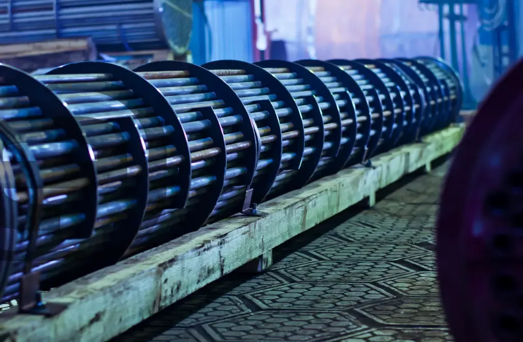
The failure mechanism due to brittle fracture in pressure equipment manifests itself as a rapid and unexpected fracture since it occurs without prior plastic deformation. In order to reduce the risk of brittle breakage, the correct evaluation and inspection of this equipment are essential to detect possible cracks that trigger these failure processes.
The usual factors that trigger the appearance of cracks in pressure equipment are usually:
- Changes at the microstructural level that reduce the ductility of the material.
- Localized concentration in sufficient quantity of certain elements, such as hydrogen, impurities or, contaminants.
- High loads that favor the tensile stresses to which a piece is subjected.
- Existence of surface defects
Typically, welded joints are areas susceptible to the appearance and propagation of cracks in pressure equipment. During the manufacture of pressure equipment, specifically, after welding between different pieces, residual stresses are generated resulting from the non-uniform temperature distributions to which these pieces are subjected during the welding process itself, especially during the cooling. These residual stresses have a significant impact on the performance of the equipment during its service life.
A good design, not only of the welded joint but also the control of the welding process will allow the shrinkage of the seam, as well as a correct cooling rate. The control of the heat input (preheating, heat input, heating between passes, advance speed, etc.) is key to reducing shrinkage stresses and reducing the cooling rate.
The presence of discontinuities in welded joints is not always visible and requires advanced inspection techniques or testing.
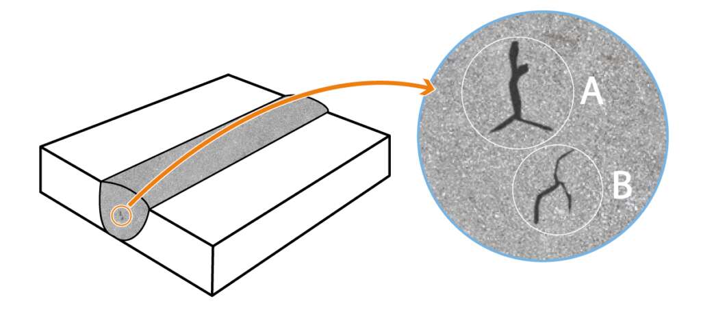
The combination of analytical methods with advanced simulation tools in the study of defect formation and propagation mechanisms to determine the stability of existing cracks in a body has meant a great advance both in the design of equipment and in the processes of manufacturing and inspection.
However, a correct characterization of the residual stresses can be a critical point in the fracture mechanics calculations in which the stability of a crack or defect is analyzed.
In the case of typical welded joints, standards such as API-579/ASME FFS-1 define certain parameters to be able to consider the effect of said stresses in the calculations. However, there are times when it is necessary to resort to advanced simulation tools to reproduce the welding process and subsequent stress relief, in order to more realistically obtain the actual residual stresses, both qualitatively and quantitatively.
In addition, with the simulation of the welding process, it is possible to identify critical areas likely to favor the propagation of the crack according to the states of maximum stresses and triaxiality, both in the weld itself and in the thermally affected area.

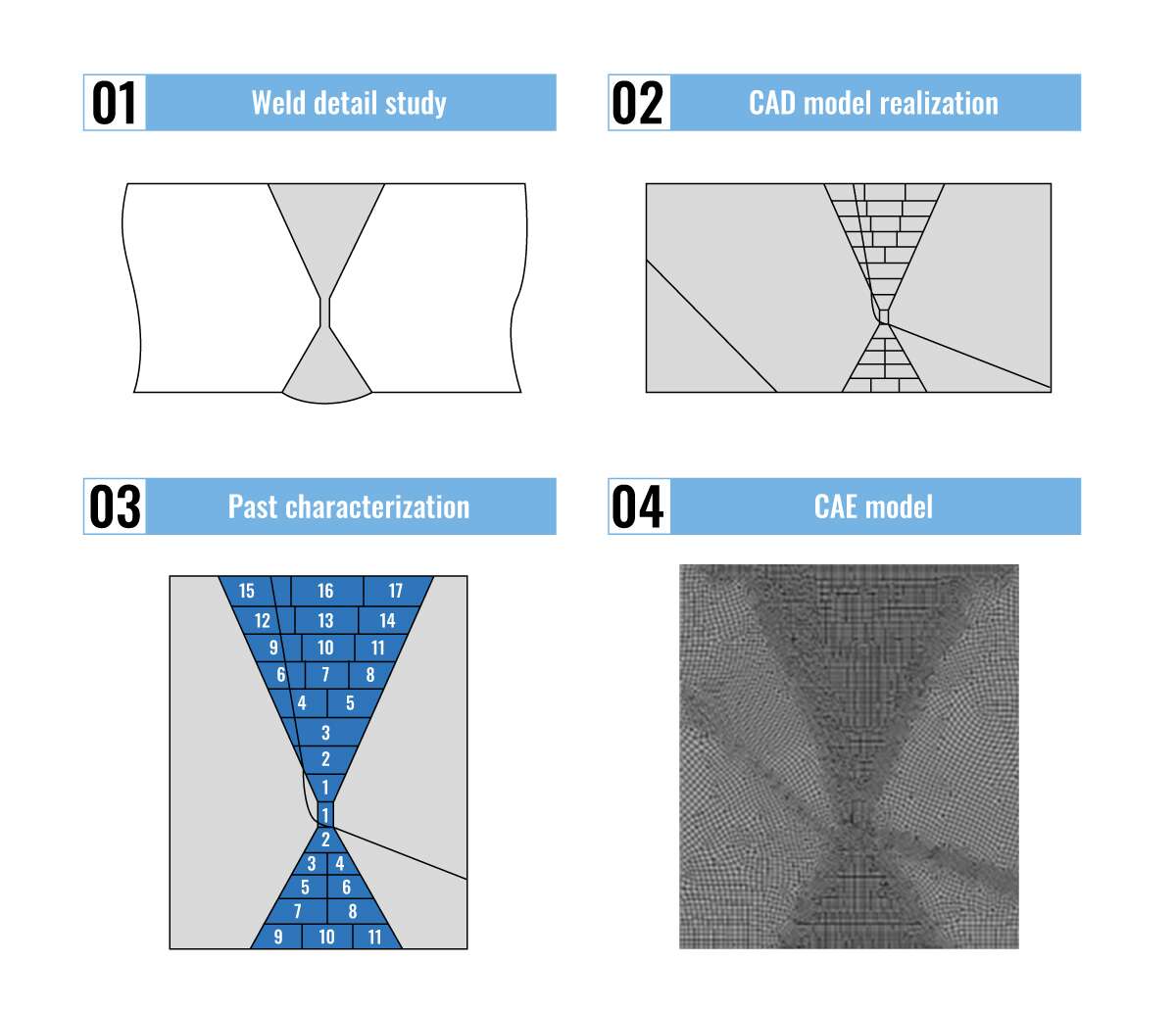
CADE has extensive experience in the simulation of welding processes using finite element calculation in which the detail of the process is characterized:
- Simulation of the contribution of the heat source during the welding process.
- Characterization of materials with thermodependent properties.
- transient heat transfer.
The goal is to obtain, on the one hand, the temperature distribution over time during the different stages of the welding process and, on the other hand, the stress and strain fields with which the residual stresses that it presents will determine the joint after final cooling.
In the following video, you can see the complete welding process, both the evolution of temperatures during the different passes, as well as the stress state both in the bead and in the thermally affected zone.
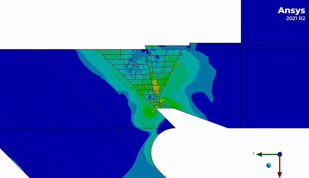
The study of structural stability considering the existence and propagation of cracks is carried out taking into account the requirements of Part 9 of the API-579/ASME FFS-1 standard, which establishes three possible levels of analysis. These three levels are progressive and the choice of one or the other will depend on the level of detail required. The acceptance criteria of levels 1 and 2 are much more conservative than those corresponding to level 3 because this level 3 is based on numerical methods such as finite elements that involve much more complex analyzes that require obtaining more accurate results.
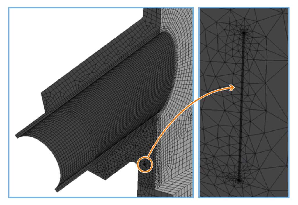
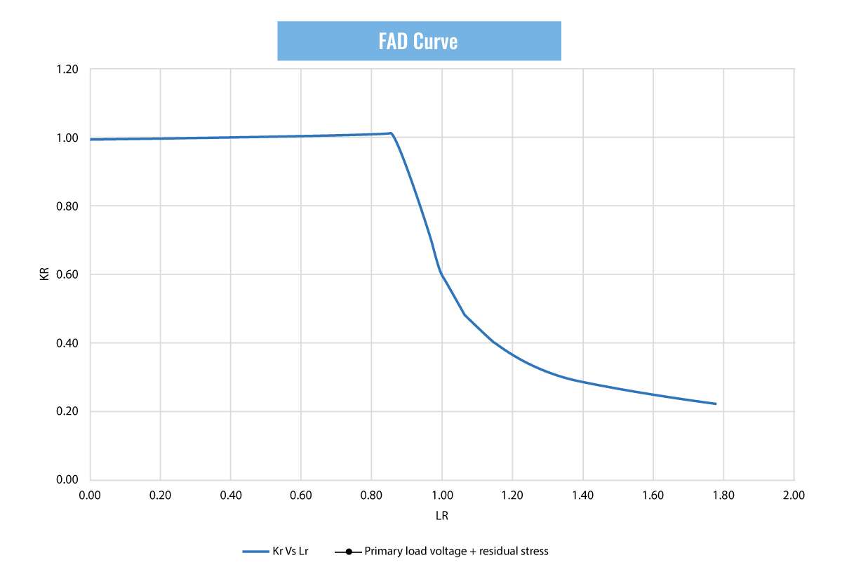
In Level 3 analyses, it is necessary to explicitly implement the crack in the calculation model in order to obtain the parameters required by the standard, such as the J Integral to obtain the FAD failure curve.
CADE has extensive experience, both in carrying out this type of study and in the development of complex simulations, which is an added value when determining the aptitude to continue in service of a piece of equipment despite existing defects.
Further information
For any query or request for additional information about our services and technologies, please complete the following form:

