Piping Design is a critical component of engineering projects and process plants. In order to get safety pipe systems, the flexibility analysis (stress analysis) is essential, because the pipe stress analysis predicts stresses in the pipeline due to thermal gradients, weights and pressures.
Stress Intensification Factors (SIF) are parameters that allow the designer to estimate the maximum stresses in the pipe line and the fatigue failure in a piping component or joints. Following paragraphs explain in detail the determination of the stress intensity factor for special geometries not covered by ASME B31.1 or B31.3 codes.
The Stress Intensification Factor (SIF) is a multiplier factor on nominal stress for typically bends and intersection components so that the effect of geometry and welding can be considered in a beam analysis (as for example calculations performed with CAESAR II software). The stress intensity factor is used in a pipe stress analysis as follow:
(Beam stress)· (SIF) ≤ Allowable Stress
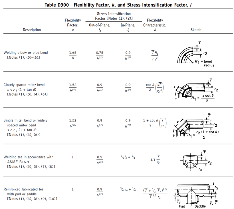
ASME piping codes (ASME B31.1 and ASME B31.3) stablish the formulation to obtain the stress intensification factor “I” and flexibility factor “k” for fitting geometries according to ASME B16.9.

For special geometries (such as valves, strainers, anchor rings, bands, etc.) or modified geometries from ASME B16.9 codes (as for instance trimmed elbows), it is necessary to obtain a valid stress intensification factor in order to avoid problems due to flexibility analysis. These values of SIF are out of the scope of design codes as ASME B31.1 or ASME B31.3. However, ASME B31J code provides the standard method for determining the stress intensification and flexibility factor required.
According to ASME B31J, there are two ways in order to obtain SIFs:
The advantage of the virtual test specimen (FEM analysis) is obvious because a real test specimen (especially for larger diameters) can be very expensive compared with the finite element analysis.
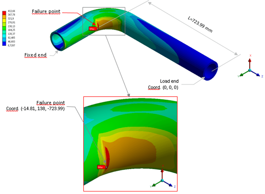
FEM analysis will allow to simulate the standard test method for determining stress intensification factors (i-factors) for metallic components as per ASME B31J and stress-life (S-N) fatigue model per Markl fatigue test curve.
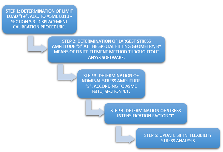
Following steps summarizes analysis methodology to determinate stress intensification factor “i”:

CADE is pleased to have participated in many relevant worldwide projects where the bi-directional calculations (between FEA analysis and pipe flexibility analysis with CAESAR II software) are required. A correct evaluation of the stress intensity factors in special geometries reduces the risk of failure in the pipeline, therefore, this part of the calculation must be essential in the flexibility stress analysis. Nowadays, most of c piping specifications require this calculation.
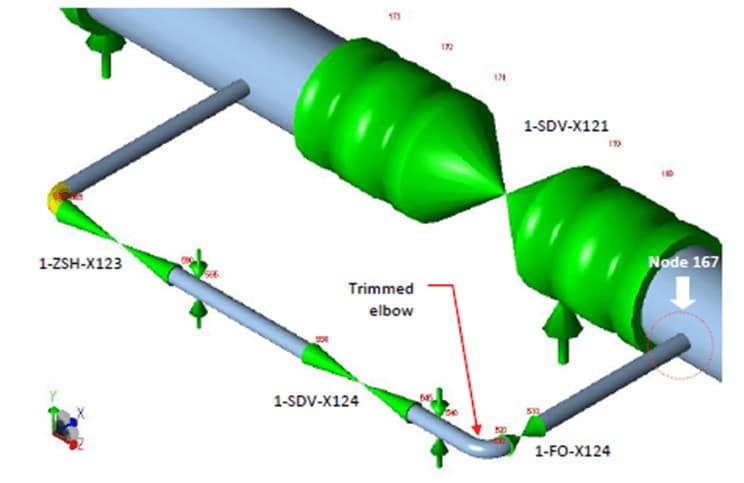
Following images show an example of project conducted by CADE, which results obtained in the determination of the stress intensity factor (SIF) in a modified geometry (trimmed elbow) was used in the flexibility calculations performed with CAESAR II software.


CADE provides engineering, simulation and consulting services aimed to assess critical plant equipment, high temperature piping, pressure vessels and structures when they are not performing as expected, a failure has occurred or their mechanical integrity and remaining life must be evaluated.
Albacete
Parque Científico y Tecnológico
Paseo de la Innovación 3, 02006 Albacete – España
Tel. +34 967 19 01 72
C/Raimundo Fernández Villaverde, 53 (Entreplanta)
28020
Madrid – España
Albacete
Parque Científico y Tecnológico
Paseo de la Innovación 3, 02006 Albacete – España
Tel. +34 967 19 01 72
C/Raimundo Fernández Villaverde, 53 (Entreplanta)
28020
Madrid – España
If you please, contact us and tell us about your project to inform you what we can do for you
We inform you about our engineering solutions