When designing a pressure vessel, the choice of the design code is one of the main decisions that must be made. Requirements of the standard should be considered, not only regarding the design conditions, but also manufacturing and inspection aspects. One of the most significant factors in this decision-making process is the potential material savings in those critical equipment that require the use of high-strength materials or in large-sized equipment, where achieving a more optimized thickness has a significant impact not only economically but also in the fabrication of the equipment.
One of the main reference standards for pressure vessels is ASME VIII, both Division 1 and Division 2. From a design and inspection perspective, if we compare both methodologies:
- ASME VIII Div 1: we obtain designs with greater thicknesses by considering a safety factor SF=3.5; however, the requirement for tests and inspections is less stringent.
- ASME VIII Div 2: the standard allows for optimization of thicknesses compared to those obtained in Division 1 by considering a safety factor SF=2.4; however, a greater number of tests and inspections are required.
Other requirements specific to Division 2 include the issuance of the User Design Specification (UDS) by the equipment owner, as well as the Manufacturer Design Report (MDR) by the equipment manufacturer; in both cases, certification of the documents is required by a Professional Engineer.
Since the 2017 edition, Division 2 has included the possibility to design a equipment referred to as Class 1, which generally considers a higher allowable stress of the material with a safety factor SF=3. This new class allows for designs by formula with more optimized thicknesses.
| Tensión admisible | ||
|---|---|---|
| División 1 | División 2 | |
| Tabla 1A/B ASME II Part D | Clase 1 | |
| Clase 2 | ||
| Tabla 2A/B ASME II Part D | Tabla 5A/B ASME II Part D | |
Therefore, when calculating equipment according to ASME VIII Div 2, it is necessary to specify the equipment class considered (Class 1 / Class 2). However, there are other differences between the two methods that go beyond the safety factor considered in the formulation and must be taken into account:
- For non-cyclic service equipment (less than 1000 cycles P-T), UDS certification by a Professional Engineer is not required; however, reviewing the UDS is still necessary. Certification of the UDS is only required when a fatigue analysis is necessary.
- For Class 1 equipment, the MDR must be certified by a Professional Engineer only when i) some component of the equipment is designed with Part 5 of the ASME VIII Div 2 standard because its design is not covered by the formulation of Part 4 of the ASME VIII Div 2 standard, ii) if a fatigue analysis is necessary, or iii) if a dynamic analysis is performed in the case of an earthquake.
- Class 1 equipment must be designed using Part 4 of the ASME VIII Div 2 standard; however, when there is no rule in Part 4 to cover a specific design, the design can be done using Part 5 of the standard, considering all the loads included in the UDS. In no case can Part 5 be used to replace Part 4 requirements.
Usually, the chosen standard for designing equipment with greater thicknesses and dimensions has been ASME BPVC VIII Div 2 due to material savings, as the design methodology on which this standard is based is more precise compared to that followed in ASME BPVC VIII Div 1. Division 2 is based on a Von Mises stress criterion, while Division 1 is based on the theory of the maximum principal stress, meaning that rupture occurs when the largest of the principal stresses reaches a limit value. Therefore, the introduction of Class 1 equipment in Division 2 provides greater flexibility in deciding which design standard is the most efficient from an economic point of view.
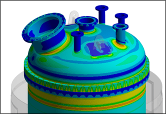
However, when seeking a more optimized and competitive design, the best option is to design the equipment using Part 5 of ASME VIII Div 2: Design by Analysis. This part of the standard is based on results obtained through numerical simulation, evaluating the protection of the different components of the equipment against failure modes such as plastic collapse, buckling, local failure, and fatigue. The standard involves performing complex calculations that consider both material nonlinearity (plastic behavior) and geometric nonlinearities.
Further information:
For any question or further information request aboud our services and technologies, please complete the following form:

