
Limitations of robotic welding when facing tolerances and distortion
Robotic welding reaches its limits when the actual position of the joint no longer matches the programmed path. Tolerances in robotic welding cannot be solved simply by increasing the accuracy of the arm or correcting points in the program. When the joint position changes from part to part, or during the weld itself, the system needs information about the real geometry. This does not necessarily mean the robot is malfunctioning. Often the root cause lies in manufacturing tolerances, assembly errors, the position of the part in the fixture or the distortion generated by the welding process itself. Conventional automation works particularly well when parts, references and manufacturing conditions remain stable. The problem appears when the system keeps following a theoretical geometry while the real part has shifted, distorted or been assembled differently.Robot accuracy does not guarantee process accuracy
One of the most common mistakes when analysing a robotic welding cell is to confuse the robot’s repeatability with the overall capability of the process. Repeatability means the robotic arm can consistently return to a programmed position. However, for the weld bead to be correctly placed, the following must also stay within tolerance:- the geometry of each component;
- the joint preparation;
- the position of the part;
- the assembly of the whole;
- the behaviour of the fixture;
- the calibration between robot, tool and part;
- the distortion generated during welding.
Main causes of tolerances in robotic welding
Dimensional tolerances are one of the main sources of variability in robotic welding. Deviations rarely have a single cause. They are usually the result of small variations accumulating throughout the manufacturing process.Manufacturing tolerances
Metal parts are not produced with mathematically perfect dimensions. Cutting, forming, bending, machining and rolling processes all work within acceptable margins. A variation may be dimensionally acceptable and yet change the position of the joint relative to the programmed path. Typical examples include:- differences in the length or width of plates;
- variation in a bend angle;
- changes in radius on curved components;
- ovality of shells and tanks;
- deviations in profiles or tubes;
- small differences between component batches.
Assembly and tack-welding errors
The joint position also depends on how components are assembled and fixed before welding. Variations may come from:- a different assembly sequence;
- irregularly placed tack welds;
- changes in the gap between edges;
- misalignment between components;
- lack of squareness;
- supports or references used differently;
- manual intervention during positioning.
Variations introduced by the fixture
The fixture positions and holds the part, but it is also subject to tolerances, wear, play and deformation. A cell can lose stability when the following appear:- worn stops;
- clamping systems with different forces;
- build-up of spatter or dirt;
- elastic deformation of supports;
- reference changes between formats;
- insufficient maintenance;
- incorrect placement of the part.
Thermal distortion during welding
Heat input causes localised expansion and contraction. As the weld progresses, the temperature distribution changes and the part may change its geometry. This can cause:- longitudinal or transverse shrinkage;
- angular distortion;
- warping;
- changes in joint gap;
- progressive displacement;
- loss of alignment on long welds;
- differences between the start and the end of the weld.
Why reprogramming the path does not always solve the problem
When a robot no longer follows the joint correctly, a common response is to modify the program points. This can work if the error is constant and repeatable — for example, when there is a fixed offset caused by a poorly calibrated reference. However, reprogramming becomes less effective when the deviation:- changes from one part to the next;
- varies along the weld;
- depends on the assembly sequence;
- appears during heating;
- differs from batch to batch;
- combines position and orientation errors.
How to detect tolerance problems in a robotic cell
Limitations do not always show up as a complete failure. They often appear as small losses of stability that become normalised in production. It is worth reviewing the process when situations like the following occur.Frequent manual corrections
The operator has to touch up points, move the part or change offsets before starting certain batches. These interventions show that nominal programming does not sufficiently represent the real geometry.Quality differences between similar parts
Two components made with the same program show different results in the position, appearance or continuity of the weld. ISO 5817:2023 sets quality levels for imperfections in fusion-welded joints, also applicable to mechanised and automatic processes. Even so, the required level must be defined according to the design, loads, material, procedure and product requirements.Over-reliance on the fixture
The cell only works properly when the part is placed within a very narrow margin. This can lead to complex fixtures, long loading times, additional checks or constant readjustment.Stoppages due to losing the joint
The robot starts the path correctly, but the torch drifts in curved areas, changes of direction, three-dimensional joints or sections affected by distortion.Difficulty introducing new part numbers
Each new geometry requires many hours of programming, testing and correction. Without perception, adapting to new parts becomes a task based mainly on points, coordinates and physical trials.Rework concentrated in specific areas
Defects or corrections appear repeatedly at transitions, ends, intersections, curves, branches or areas where tolerances accumulate. This pattern may indicate that the problem is not only in the welding parameters, but in the relationship between the programmed path and the actual joint position.The real part is not the CAD model
CAD represents the nominal geometry. It is an essential reference for design, simulation, manufacturing and programming, but it does not contain all the variability that will appear in production. Between the model and the final part come:- manufacturing processes;
- dimensional tolerances;
- assembly;
- tack welding;
- clamping;
- handling;
- heating;
- shrinkage.
What better fixturing can solve, and what it cannot
Fixturing remains essential. An adaptive solution does not justify poor preparation, nor does it remove the need to control assembly. A well-designed fixture can:- establish clear references;
- reduce displacement;
- control certain tolerances;
- support repeatability;
- limit distortion;
- simplify loading and unloading;
- improve process safety.
- the inherent variability of components;
- the ovality of large parts;
- accumulated deviations;
- differences between batches;
- movement caused by heating;
- variation in a three-dimensional path;
- changes in gap along a joint.
How seam tracking changes the approach
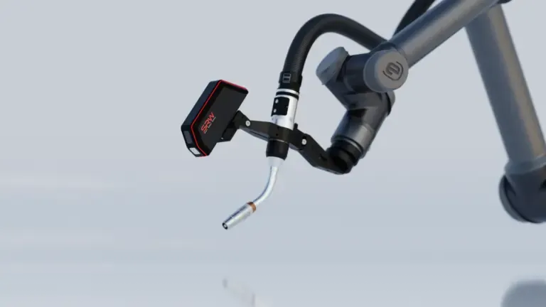
Seam tracking brings in information about the actual position of the joint. Instead of assuming that the joint lies exactly at the programmed coordinates, the system uses sensors to locate it and calculate the necessary corrections. A vision architecture can obtain three-dimensional information by triangulation, calibrate the relationship between camera and robot, and transform the detected position into the coordinate system used by the manipulator. This approach is used to capture the real path and correct the motion during welding. Depending on the application, different strategies can be used.Locating the joint before welding
The system scans the part before starting and generates or corrects the path. This approach suits cases where geometry varies between parts but remains relatively stable during the weld.Tracking during the process
Sensors gather information while welding is under way and the system applies corrections as it progresses. This strategy matters when the joint position changes along the path or when thermal distortion progressively alters the geometry.Combining scanning and adaptive control
The part is located first and then monitored during the operation. This combination addresses both initial assembly differences and the variations that appear during the process.What to analyse before adding 3D vision
Vision should not be added just because the cell shows deviations. The problem must first be characterised.Real variability of the part
Measure how much the joint changes:- between units;
- between batches;
- along the weld;
- before and after tack welding;
- during the welding sequence.
Joint type and geometry
Not all joints are equally easy to detect. The following should be analysed:- geometry;
- gap;
- preparation;
- orientation;
- material;
- surface finish;
- accessibility;
- reflections;
- presence of spatter;
- interference with the torch.
When the deviation appears
It is necessary to distinguish whether the error exists before welding or appears during heat input. This difference determines the choice between prior scanning, real-time tracking or a combination of both.Required correction range
An adaptive system should not be seen as an unlimited ability to weld any part. Acceptable margins must be defined for:- displacement;
- orientation;
- gap;
- height;
- rate of change;
- accessibility;
- process stability.
Quality requirements
The control strategy must be linked to the acceptance criteria that apply to the product. It is not enough for the robot to visually follow the joint. Parameters, torch position, speed, arc stability and the welding procedure must also remain within validated conditions.Integration and safety
Adding sensors, positioners, vision systems and new motion strategies changes the whole cell. ISO 10218-2:2025 covers safety requirements for the integration, commissioning, operation, maintenance and decommissioning of industrial robot applications and cells. The assessment must consider the integrated system, not just the robotic arm.Related CADE services: CADE SRW: intelligent robotic welding · Welding engineering · Smart Factories Further information: International Institute of Welding (IIW) You may also be interested in: What is intelligent robotic welding and how does it work? · Intelligent robotic welding CADE SRW