Flanged Joint Leak Tightness Analysis: Calculation and FEA

Flanged joint leak tightness analysis must consider both the stress state of its components and the gasket’s ability to maintain a uniform seal. In complex configurations, design by analysis makes it possible to assess phenomena that simplified analytical methods may not adequately represent.

Why is flanged joint leak tightness analysis necessary?

The assessment of critical flanged joints is common in both piping systems and equipment connections. Its purpose is to evaluate the stress state of the components forming the joint and verify the leak tightness of the assembly.

Leak susceptibility depends on several factors, including the flange type, selected gasket and applied tightening torque. The analysis should therefore consider geometry, materials, design loads and assembly conditions as an integrated system.

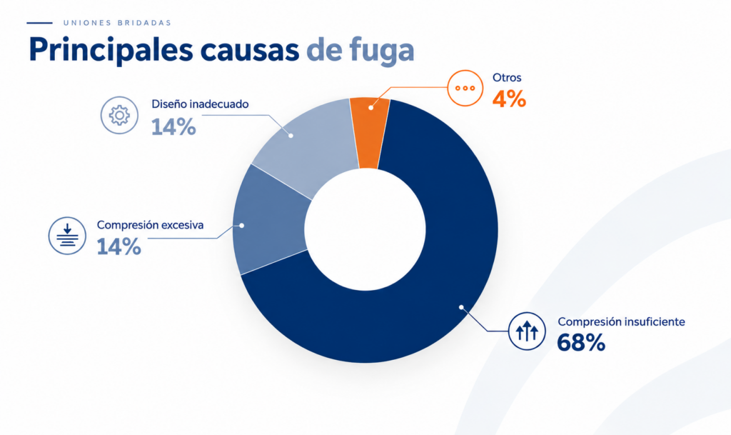
Main causes of flanged joint leakage

  • High mechanical loads and/or thermal shocks that cannot be accommodated by the system due to insufficient flexibility, or that cause excessive deformation of the flanged joint components.
  • Thermal gradients not considered during the design phase, which may lead to loss of bolt preload or unexpected deformation of the different joint components.
  • Incorrect tightening torque. Insufficient tightening may result in inadequate sealing between the flange and gasket, while excessive tightening may cause excessive gasket deformation and highly stressed areas in the flange.
  • Vibrations generated by components installed in the piping system.
  • Corrosion resulting from inappropriate material selection, which may cause uneven seating between the gasket and flange.
  • Misalignment or assembly errors, which may generate additional loads and affect both the structural integrity of the joint and the uniform seal between the gasket and flange.
principales causas de fuga

Gasket compression and separation forces

Assessing the leak tightness of a flanged joint requires evaluating the distribution of contact pressure between the gasket and flange. Proper design requires the gasket to remain sufficiently compressed to maintain a uniform, leak-tight seal.

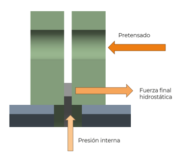
The initial gasket compression is reduced by internal pressure and by the tendency of the flanges to separate due to the hydrostatic end force.


Figure 1. Forces acting on a flanged joint.

Flanged joint calculation: scope and limitations

Analytical validation of flanged joints is covered by commonly used design codes for pressure equipment, including ASME BPVC Section VIII, Divisions 1 and 2, and EN 13445-3. ASME PCC-1 also provides recommendations regarding bolted flange joint assembly and bolt-tightening procedures.

However, analytical methods have limitations that should be considered when designing a flanged joint:

  • They do not account for the effects of thermal gradients and/or external loads.
  • They do not specify maximum and minimum gasket stresses.
  • They assume a uniform stress distribution over the gasket surface in both radial and circumferential directions.
  • They consider a limited range of gasket materials, such as semi-metallic or graphite gaskets.
  • They assume constant tightening over time and do not account for long-term preload losses.
  • They do not incorporate the potential influence of geometric discontinuities close to the joint, such as nearby nozzles or supports, or misalignment resulting from improper assembly. These factors may generate non-uniform pressure distributions at the flange-gasket interface.
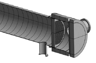
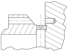
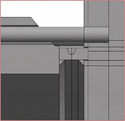
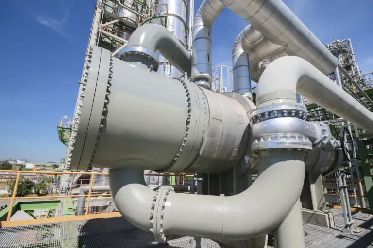
  • They apply to standardised flange configurations and have limitations for non-conventional or large-diameter joints, such as those used in certain heat exchanger headers.
Imagen4
Imagen52
Imagen62

Figure 2. Non-conventional flanged joint in a heat exchanger.

When to use design by analysis

Design by analysis is recommended when an approach based exclusively on analytical formulas may introduce simplifications or non-conservative assumptions that do not adequately represent the actual behaviour of the joint and could compromise its performance or structural integrity.

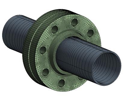
Numerical simulation of flanged joints

For critical applications and components, numerical simulation models provide a more detailed assessment of flanged joint leak tightness, considering both structural behaviour and the contact conditions between the gasket and flange.

This approach enables structural analysis and flanged joint leak tightness to be assessed as part of a broader evaluation of equipment integrity and performance.


Figura 3. Detalle del modelo de una unión bridada.

Gasket-to-flange contact pressure distribution

One of the main advantages of design by analysis over conventional formula-based design is its ability to predict the pressure distribution between the gasket and flange more realistically.

The numerical model can identify non-uniform pressure distributions in both radial and circumferential directions.

Detecting these gradients is essential for evaluating joint leak tightness and identifying areas with insufficient contact pressure and, consequently, a greater susceptibility to leakage.

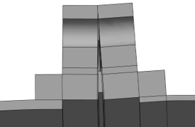
Figura 4. Deformación de una unión bridada.
Figure 4. Deformation of a flanged joint.
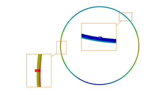
Figura 5. Distribución no uniforme de presión entre la junta y la brida.
Figure 5. Non-uniform pressure distribution between the gasket and flange.

Structural integrity assessment

In addition to leak tightness analysis, the stress state of the joint must be assessed.

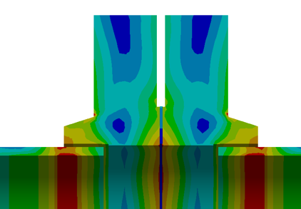
The evaluation should verify compliance with the requirements of the applicable design code for the failure modes defined by the code, including protection against plastic collapse, local failure and cyclic loading conditions such as ratcheting and fatigue.

Figura 6. Estado tensional de una unión bridada.

Bolt-tightening sequence

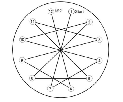
Numerical simulation can also be used to assess the bolt-tightening sequence and reproduce the order, magnitude and evolution of the preload applied during assembly.

Sequential and multi-stage tightening, including potential re-tightening operations, may generate load distributions that significantly affect the structural behaviour of the joint.

Potential effects include areas with insufficient contact pressure between the flange and gasket and localised high stress concentrations.

Figura 7. Ejemplo de secuencia de pretensado para una unión bridada de 12 pernos según ASME PCC-1.
Figure 7. Example of a bolt pretensioning sequence for a 12-bolt flanged joint according to ASME PCC-1.

Engineering, Simulation and Integrity applied to flanged joints

CADE approaches flanged joint analysis from a multidisciplinary perspective, integrating pressure equipment calculation, advanced simulation and structural integrity.

The combination of analytical methods and numerical models enables the structural behaviour of the joint, gasket contact pressure distribution and the conditions that may compromise its leak tightness to be evaluated together.

This approach is complemented by CADE’s experience in plant and process engineering and industrial facilities, providing a practical understanding of design, assembly and operating conditions.

The objective is to establish robust engineering criteria for assessing critical flanged joints and supporting technical decision-making during equipment design, evaluation and operation.
Need to assess a critical flanged joint?

We assess its structural behaviour and leak tightness using both analytical calculations and advanced numerical simulation.

Picture of Carmen García Jiménez

Carmen García Jiménez

Albacete

Parque Científico y Tecnológico

Paseo de la Innovación 3, 02006 Albacete – España

Tel. +34 967 19 01 72

Madrid

C/Raimundo Fernández Villaverde, 53 (Entreplanta)

28020

Madrid – España

Albacete

Parque Científico y Tecnológico

Paseo de la Innovación 3, 02006 Albacete – España

Tel. +34 967 19 01 72

Madrid

C/Raimundo Fernández Villaverde, 53 (Entreplanta)

28020

Madrid – España

Contact us

I guess you are interested in what we do

If you please, contact us and tell us about your project to inform you what we can do for you

Can we call you?

We inform you about our engineering solutions