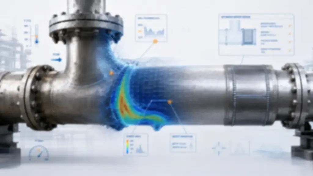

How to deal with wall thickness loss in critical equipment
Wall thickness loss in operating plant equipment is one of the defects most frequently detected during in-plant inspections. This phenomenon, generally associated with corrosion and/or erosion, poses a significant risk to the structural integrity of assets in sectors such as Oil & Gas, petrochemicals and power generation.
Why does wall thickness loss occur in equipment?
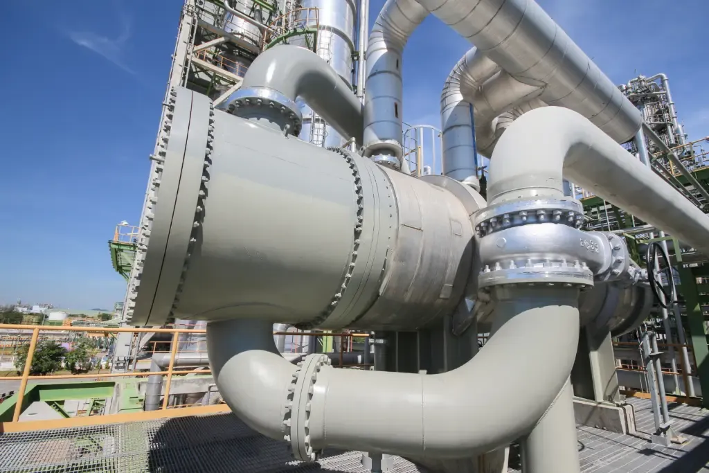
Once equipment enters service, it is exposed to severe conditions that can promote progressive wastage of the base material. As a result, the nominal thickness of components such as piping, pressure vessels, heat exchangers and storage tanks is reduced.
This thickness loss can be due to different causes, most notably:
- Chemical or electrochemical corrosion caused by the interaction of the stored fluid or the external atmosphere with the metal.
- Localised attack or pitting.
- Operating conditions, such as pressure or temperature changes and variable load cycles.
- Inadequate protection due to lining failures, absence of coatings or failures in the cathodic protection system.
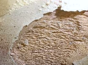
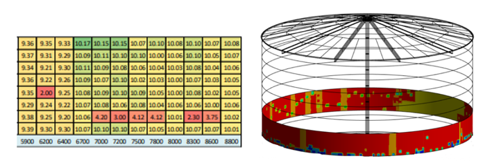
Inspection and monitoring of wall thickness loss
When signs of wall thickness loss are detected in in-service equipment, it is essential to launch and plan inspection and monitoring programmes.
These programmes should make it possible not only to characterise the damage, but also to determine its extent and severity. To this end, they may include techniques such as:
- Ultrasonic testing (UT) for thickness measurement.
- Corrosion mapping to identify the affected areas.
- Analysis of historical data to assess the degradation rate.
- Integrity assessment studies such as those set out in API 579/ASME FFS-1.
These studies support decisions on the corrective actions needed to ensure the continued service of the affected equipment.
Integrity assessment according to API 579/ASME FFS-1
Part 5 of API 579 / ASME FFS-1 sets out a specific methodology, structured in three levels, to assess the structural integrity of equipment exhibiting this type of flaw. Its purpose is not only to determine whether the equipment can remain in service or whether repair measures are required, but also to determine its remaining life.
The three assessment levels defined by the code are:
Level 1
Simplified assessment using analytical formulas and geometric criteria
Level 2
Detailed assessment considering the exact geometry of the affected area
Level 3
Advanced analysis in which numerical simulation is the key tool.
- Level 1 – Simplified assessment, using analytical formulas and geometric criteria to compare the measured thickness with the minimum required thickness. It is a quick assessment for an initial decision.
- Level 2 – Detailed assessment, considering the exact geometry of the affected area through more accurate calculations and less conservative criteria.
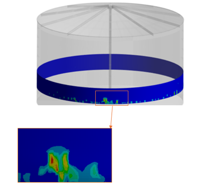
- Level 3 – Advanced analysis, in which numerical simulation is the key tool for assessing structural integrity. The thickness loss is modelled and its effect on stresses and strains under real operating conditions is studied.
When is a Level 3 assessment required? What does it add?
These are two of the most common questions in the field of structural integrity assessment.
A Level 3 assessment is recommended where Level 1/2 assessments are inconclusive or overly conservative, so that the only remaining option would be to replace the equipment. When the component under study is critical, repairs need to be optimised because of their high cost, and sufficient inspection data are available for a more realistic characterisation of the damage, it is advisable to proceed directly with this type of study.
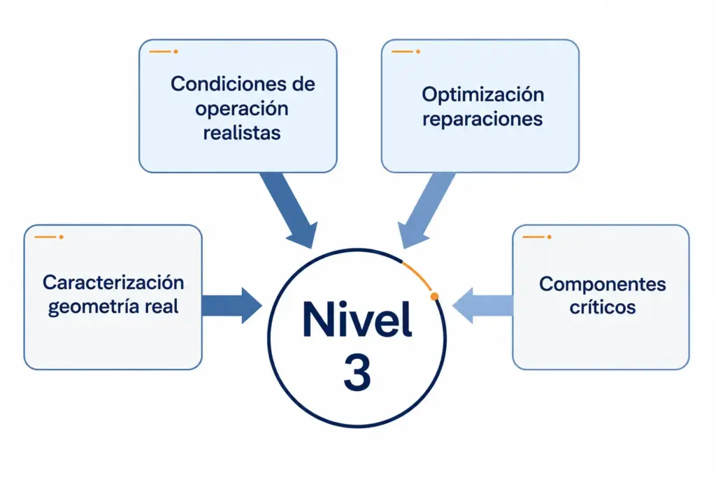
Level 3 analysis for decision-making
CADE has the capability to undertake assessments that go beyond traditional conservative methods. This makes it possible to deliver more accurate solutions with a comprehensive approach, making Level 3 analyses a routine tool for validating the structural integrity of in-plant assets.
Process automation and the use of in-house tools allow this type of work to be carried out efficiently, streamlining the workflow from data analysis through computation times to the post-processing of results.
This translates into achievable, realistic timescales adapted to the operational reality of the plant, and has a direct impact on decision-making. The analysis makes it possible to manage risk more efficiently and, in many cases, to justify the life extension of critical equipment, avoiding premature replacements and reducing operating costs.