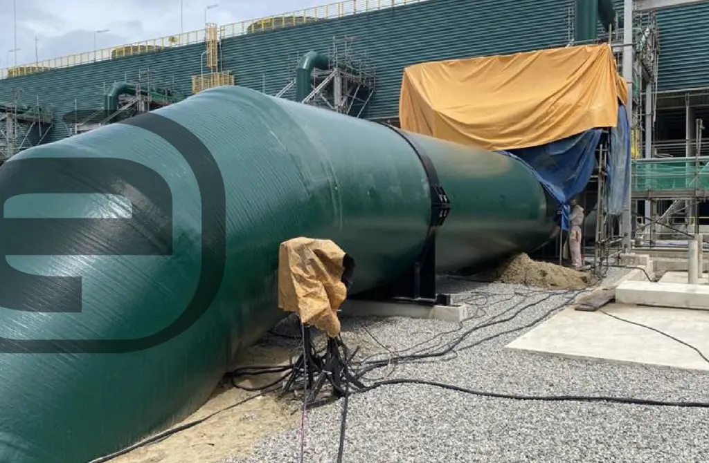
There are many sectors (chemical and process industry, naval, aeronautical or food sector) and industrial applications in which it is necessary to design and validate equipment made with special materials (FRP- Fiberglass Reinforced Plastic), due to to the special corrosion resistance requirements for which they have to provide service. This is the case of pressure vessels, conduits, pipes or storage tanks, among others, etc.
Their design and construction are regulated by different American and European standards; include, among others:
- ASME BPVC Section X, Fiber-Reinforced Plastic Pressure Vessels, which covers the design and construction of pressure vessels, manufactured using FRP (carbon, glass or aramid fiber reinforced plastic laminates) technology, for internal pressures above 15 psig , and external between 0 and 15 psig. It classifies the equipment in Class I, Class II and Class III.
- ASME RTP-1 Reinforced Thermoset Plastic Corrosion-Resistant Equipment, which is focused on tanks and vessels with internal or external pressures up to 15 psig. Type I, type II and type X laminates.
- The standards ASTM D-3982 (Contact Molded Duct and Hoods), ASTM D-6041 (Contact Molded Pipe), ASTM D-3299 (Filament Wound Tanks) and ASTM D-4097 (Contact Molded Tanks).
- The European standard BS EN 13923 Filament-wound FRP pressure vessels. Materials, design, manufacturing and testing, for pressure vessels and gas cylinders subjected to pressures below 20Mpa and at temperatures between -30 and 120ºC.
BS EN 13923 GRP tanks and vessels for use above ground.
In many cases, these codes and standards require an accurate determination of the stress and strain states of laminated components (FRP), for their validation and certification, as is the case of class II equipment according to ASME Section X. This can be done perform using analytical calculations or by simulation.
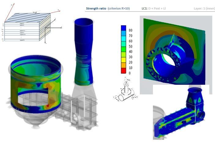
The analysis of these stresses and deformations, as well as the orientation of the efforts with respect to the orientation of the fibers, is often complex or unapproachable by means of a standard analysis by formula, being necessary the use of simulation methodologies such as the finite element method. (FEM). This is the case of special geometries or areas with discontinuities: openings, supports, equipment with non-cylindrical or spherical geometries, reinforcements, etc.
The direction and value of the deformation and stresses in the sheet, as a result of the finite element calculation, are used to validate each component against the requirements and failure criteria of the corresponding code: stress, deformation or buckling limitations. These calculations are made for different operating conditions, lifting and transport situations, wind and earthquake conditions, etc.

The simulation tools through FEA analysis are used in a complementary way to the design carried out through analytical calculations (by formula), since they are of great help for the optimization of materials, the analysis of construction details, or to anticipate possible deficiencies in the equipment, even in the case of those whose certification is carried out employing prototypes that are destroyed during the test (such as equipment built under the ASME RTP-1 standard).
FEM analysis
By using FEM analysis software, it is possible to accurately characterize the mechanical and thermal properties of laminated materials, according to the type of manufacture (filament winding, tape wrapping, spray up, vacuum infused …), the matrix material, and according to the typology and orientation of the reinforcing fibers.
The reference code will require in certain cases the prior performance of tests to determine the mechanical properties of the sheets, according to the direction of the load.

At CADE we have the tools and experience necessary for the design and calculation of complex equipment made with FRP materials, either by formula calculation and / or by FEM simulation.
Further information:
For any question or further information request about our services and technologies, please complete the following form:


