The installation of structures/solar trackers for energy generation, by small companies to large energy producers, has been very common for more than 10 years. This has led to the need for validation of the structures that support photovoltaic panels.
Eurocode, a worldwide reference structural validation code, does not implicitly contemplate the calculation of this type of structure. For this reason, CADE has developed a proven work methodology under the umbrella of the different structural codes for the analysis and validation of this type of structure.
The CADE workflow for the validation of the structures that support the photovoltaic panels is as follows, and depends on the needs/reference documentation provided:

Next, all the phases proposed in the flowchart necessary for the validation of the structures/solar trackers are described:
Content
Review and study of the information provided by the cliente
At this stage, all the documentation provided by the client regarding the structures/solar trackers is reviewed, and a report of conclusions is subsequently issued. This information serves as a starting point for making the 3D models of the structures/trackers, which are necessary to perform the structural analysis.
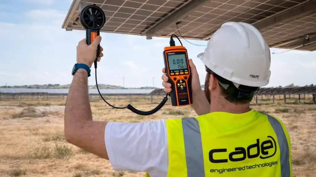
On site measurement to obtain geometric models
In the event that general and detailed plans of the structures/trackers are not available, a visit to the site is necessary, in order to carry out data collection and measurements of all the components of the structureIts goal is to obtain all the data about the design of these structures: types of profiles, thicknesses, positions, drive systems, details of bolted joints, panel anchoring systems.
This measurement and obtaining of design data serves as a starting point for the realization of the 3D models of the structures/trackers, necessary to perform the structural validation.
Determination of wind loads according to Eurocode
There are several possibilities to obtain the wind loads:
- Calculation of pressure coefficients by wind tunnel. In the event that the client considers it necessary to determine wind loads from wind tunnel tests, CADE processes these loads based on the reports obtained through this methodology.
- Calculation of pressures on structures/solar trackers by means of fluid dynamic analysis (CFD): Methodology of recognized prestige by which it is not only possible to calculate the pressure coefficients due to a certain wind load, but also the possibility of carrying out studies on the configuration of the photovoltaic field, determination of optimum angles of inclination or height of the structure with respect to the ground, among others.
- Calculation of pressure loads using Eurocode 1 specifications. To obtain wind loads through Eurocode 1 specifications, the wind speed design specified by the code for the location area is considered, or if failing that, the client may specify other speeds depending on whether they have wind studies in the área or not. These studies must be contrasted.
Should the consideration of concealment factors be required for further structural optimization, these can be obtained by CFD analysis.
Obtaining orographic coefficients
In the event that there is no study of the orographic coefficients, necessary for the consideration of wind loads, a detailed study of said coefficients is performed. This study is considered necessary if:
- Required by the client.
- After reviewing the topographic plans or after visiting the plant, it is observed that the terrain has orographic accidents that may influence the determination of the orographic coefficients.
- After reviewing the calculations provided by the client, it is observed that this study is necessary, since they have assumed little conservative coefficients.
Modeling and Simulation of structural behavior of the tracker
In this phase, a modeling of the solar structure is carried out in order to validate against the design code.
To do this, the following tasks are performed:
I. Modelling of the solar structure
Once the geometric data of the solar trackers/structures are obtained, from the manufacturer’s plans or after performing measurements in the field, a global 3D model is made, through the geometric characterization of all the components of these structures ( pillars, torsion tubes, frames, purlins, panels) in order to evaluate the global behavior of said structure through finite element analysis.
For the realization of this global model two situations can occur:
- Geometric simplifications are used, so that the profiles of the structure are characterized by beam elements, while the solar panels are characterized by surface-type elements. The joints are not taken into account in detail since the structure is studied from a global point of view.
- E Global study using the model described in the previous section and, in a complementary manner, detailed models to evaluate the behavior of critical zones (joints). To do this, the models are made through the use of surface/solid elements that allow the detailed geometric characterization of all the elements of the joint.
In these calculation models, the mechanical characteristics of the photovoltaic panels provided by the client are implemented.
II. Analysis of loads and combinations
Snow, earthquake, wind and self-weight loads are taken into account in the analysis according to the pre-registrations of Eurocode 1.
The load hypotheses and their corresponding increase coefficients are obtained according to Eurocode 1.
III. Performing a static analysis of the solar tracker/structure, using finite element analysis (FEM)
An analysis by finite elements of the complete structure is carried out to evaluate the global behavior of the structure, based on the global model made in section I.
The analysis is performed with the ANSYS WORKBENCH calculation software in its latest version.
The objective is to identify the critical points of the structure and verify that the structures meet the minimum requirements established in the code.
For this, the following types of analysis are carried out:
- Modal analysis, to determine the natural frequencies of the tracker and its associated deformation modes. The objective of this analysis will be to evaluate the stiffness of the structure and use these values to determine the static and dynamic loads.
- Static structural analysis, to evaluate the global behavior of the structure / tracker, considering the mechanical loads that act on the structure (own weight, wind, snow and earthquake). The aim of this analysis is to determine the states of stress and deformation of the different components of the tracker, in order to subsequently validate them against the admissible stresses determined by the Code.
- Linear buckling analysis, to determine the buckling modes (global buckling, buckling, warping, local buckling) of the structure or its components and the safety factors associated with each mode.
Verification of the main elements of the structure
Once the stress states in each component and area of the structure have been determined, the utilization coefficients are obtained in each of them by comparing the design stresses against the allowable stresses established in Eurocode 3.
In a complementary way, it is verified that the deformations obtained after the calculations do not exceed the deformation limits established by the code for each of the components of the structure.
V. Verification of joints or shaft sections
A finite element analysis of each of the joints considered is carried out, through the detailed modeling of all the components of the joint, using the detail models described in I. The detail models include the joint pieces, reinforcements and the screws. They are modeled with Shell elements and solid elements in order to faithfully characterize the geometric detail of said joints.
For the verification of the joints, the design stresses obtained from the finite element models of the detail models are used, verifying the structural integrity of the pieces, and in a complementary manner, the verification of the bolts according to the criteria of Eurocode 3
VI. Study of the stability of the tracker against aeroelastic phenomena
For the evaluation of the stability of the tracker against aeroelastic phenomena, the criteria of Eurocode 3, UNE-EN 1991-1-4 in Annex E are applied.
- Torsional gallop
- Flaming
- Torsional divergence
- Vortex shedding
- Batting vibration
Implementation of corrective measures
In the event that, once analyzed, some of the components do not meet the requirements of the code, the client is informed and the necessary improvement measures are proposed so that said elements meet the prescriptions established by the code.
Further information
For any query or request for additional information about our services and technologies, please complete the following form: